
Understanding Audio Signal Flow Diagram for Live Sound
In live audio production, each sound has a path to reach the audience. From concerts to conferences, worship to corporate events, it is crucial to know that path, no matter what kind of event you are planning, to get clear and reliable audio. An audio signal flow diagram can help engineers visualise the flow of audio to ensure proper setup, routing, and troubleshooting.
This audio engineering guide covers the basics of live sound signal flow, the use of the signal flow graph control system, and how they can be used to manage modern audio systems.
What Is a Signal Flow Diagram?
A signal flow diagram is a schematic diagram that displays the flow of audio signals from the source to the destination. In a signal flow diagram, audio, each device is represented in succession to make it easy for the engineers to follow the signal flow.
A signal flow diagram helps:
– Simplify complex audio systems
– Improve troubleshooting
– Support system documentation
– Reduce setup errors
The structured approach used in a signal flow graph control system follows a similar principle by showing how signals move between connected points.
History and Evolution of Audio Signal Flow Analysis
Signal flow analysis was first used in electrical engineering applications, and subsequently emerged as a common way to document audio systems. As technology changed, the signal flow diagram became a must-use planning tool for audio engineers.
The signal flow graph control system approach and today’s advanced signal routing techniques help users handle more complex audio environments.
Domain of Application
In any place where audio signals must be accurately routed and controlled, a signal flow diagram is widely used.
Common applications include:
– Live event production
– Recording studios
– Broadcast facilities
– Corporate AV systems
– Educational institutions
– Houses of worship
A signal flow diagram live sound setup comes in handy, particularly when dealing with multiple microphones, monitor mixes, and speaker zones. The signal flow graph control system is also used in automation, robotics, and telecommunications, among other areas.
Basic Signal Flow Graph Concepts
Basic signal flow graph control system concepts help engineers understand signal routing and system behaviour.
Key elements include:
– Nodes – Points where signals exist
– Branches – Paths connecting nodes
– Gain – Signal amplification or reduction
– Direction – The path a signal follows
These concepts form the foundation of a signal flow diagram and help organize audio systems logically.
Terminology and Classification of Signal Flow Graphs
Several terms are associated with a signal flow graph control system.
Source Node
The starting point of a signal.
Sink Node
The final destination of a signal.
Forward Path
The direct route between input and output.
Feedback Loop
A path that returns information to an earlier stage.
Common classifications include:
– Open-loop systems
– Closed-loop systems
– Linear systems
– Non-linear systems
Understanding these terms makes a signal flow diagram easier to interpret and apply.
Choosing Variables in Audio Signal Flow
Creating a useful signal flow diagram starts with selecting the right variables.
Common variables include:
– Input channels
– Output channels
– Signal levels
– Processing stages
– Routing destinations
A microphone signal can, for instance, go through a Stage Box to a mixing console. Clear variable selection makes a signal flow diagram more effective for system planning and troubleshooting.
Basic Components in an Audio Signal Chain
Every signal flow diagram audio layout contains several key components.
Audio Sources
These generate the original signal:
– Microphones
– Instruments
– Playback devices
Connections
Signals travel through an Audio Connector that links devices together.
Mixing Console
The mixer controls levels, EQ, dynamics, and routing.
Signal Processing
Processing devices include:
– Equalizers
– Compressors
– Gates
– Effects processors
Amplifiers and Speakers
Amplifiers increase signal strength before it reaches loudspeakers.
The structured layout of a signal flow graph control system helps engineers understand how these stages connect within the audio signal chain.
Understanding Live Sound Signal Flow
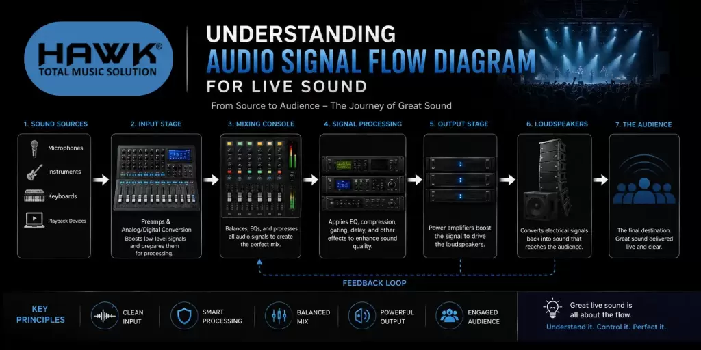
A signal flow diagram live sound workflow shows how audio travels through a live production system.
A basic path follows:
Microphone → Mixer → Processing → Amplifier → Speaker
In larger events, effective Audio Signal Routing allows signals to be sent to multiple destinations, such as:
– FOH speakers
– Monitor systems
– Recording feeds
– Broadcast outputs
– Streaming platforms
A modern professional audio system may include digital mixers, DSP processors, audio networking, and loudspeaker management systems. A signal flow diagram helps document these connections and maintain consistency during live productions.
Many routing decisions can also be analysed using principles from a signal flow graph control system.
Common Signal Flow Problems and Troubleshooting
Even well-designed systems can experience problems. A signal flow diagram helps engineers trace faults quickly.
No Audio
Possible causes:
– Muted channels
– Incorrect routing
– Faulty cables
– Power issues
Distorted Audio
Potential causes:
– Excessive gain
– Clipping
– Overloaded microphone preamps
Feedback
Occurs when microphones capture amplified sound from speakers.
Signal Dropouts
Often caused by:
– Loose connections
– Damaged equipment
– Wireless interference
Many troubleshooting methods follow the same logical approach used in a signal flow graph control system, where each stage is checked in sequence.
Best Practices for Audio Signal Flow
Adhering to best practices ensures reliability and better sound quality.
Keep Documentation Updated
Every signal flow diagram should reflect current routing and equipment.
Label Inputs and Outputs
Clear labelling reduces setup errors.
Maintain Proper Gain Structure
Balanced gain staging minimises noise and distortion.
Simplify Signal Paths
Avoid unnecessary processing whenever possible.
Test Before Events
Verify routing and signal paths before going live.
These practices support a reliable, sound reinforcement system and help maintain efficient workflows. The organised structure of a signal flow graph control system can further improve signal management.
Conclusion
Signal flow diagrams are an indispensable instrument to comprehend audio routing, resolve problems, and optimise performance. It can be used in a studio, broadcast facility, or live venue to obtain a clear understanding of the way signals flow through a system.
A signal flow diagram, when used with the concepts of a signal flow graph control system, aids the engineer in creating efficient, scalable, and reliable audio systems.
Frequently Asked Questions
1. What is a signal flow diagram in audio engineering?
A signal flow diagram is a visual map showing how audio signals travel through equipment from source to output.
2. Why is a signal flow diagram important in live sound?
A signal flow diagram live sound setup helps engineers understand routing, identify faults, and improve system performance.
3. What is a signal flow graph control system?
A signal flow graph control system is a graphical method used to analyze signal movement between connected variables.
4. How does a signal flow diagram audio layout help troubleshooting?
A signal flow diagram audio layout allows engineers to follow the signal path and quickly locate routing or equipment issues.
Add Comment